
in the beginning
It is nearly 200 years since two brothers designed and built one of the most extraordinary machines in the history of engineering. It drove their flax mill hidden in a remote Derbyshire valley - a mill that exists to this day.
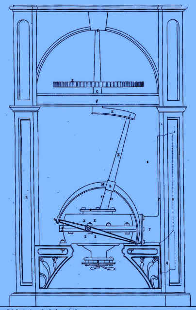
Very few people have heard of their invention and, of those that have, very few understand how it worked. Powered by high pressure water from higher up the valley it produced rotary motion yet it did not itself turn. Essentially, if it had only two parts and it had no valves to control the flow of water.
Any engineer understanding the principle of the engine would almost certainly say it would not work or, even if it did, it would be extremely inefficient. And indeed, when other pioneers adapted the design for steam working, many engineers of the time were scathing. Although several hundred were built in the first half of the 19th century, the sceptics were eventually proved to be a right.
At least they were partly right. Whilst it's use as a prime mover virtually died out after 1850, today a device based on the original concept is in widespread use in the Western World. If in fact there is a better than even's chance that there is one in your home if you live in Europe or North America.
And, against all the odds, this arcane design has once again recently emerged as a power plant.
This site will tell you all about the origins of the engine and trace its history over the centuries. Hopefully you might even understand how it works!
the lion that roared
In those permanently sunlit days before World War 2 before I was old enough to go to school, my grandfather, Philip Wright, often used to take me a walk down into Two Dales, a village some 2 miles north of Matlock. From there we would walk past the huge flour mill into Ladygrove, a dark and precipitous valley which a ran up to the surrounding moors.
Invariably we would pause by the small terraced cottages just before the mill that loomed above them. Collectively known as Brookbottom, the end cottage was once a grocer's shop.More importantly it was the place where my grandfather had been born in 1859. The mill had not always been a flour mill. In those days it was owned by the Dakeynes and manufactured flax. Philip's father had worked there as a flax dresser whilst my great grandmother ran the shop. I could not believe so many people lived in that little house.
The next stop was at the other end of the mill where a huge pile of beautifully dressed gritstone lay out the side of the lane. This, I was told, was what was left of the engine house. Grandfather never forgot to point out where the line shaft which drove me machinery in what he called the old mill had crossed the road. He remembered the engine working. Nobody ever saw it but the village boys were in awe of the great roar that it emitted as it worked. They called it the "Romping Lion".
ปั๊มลมมือสอง ผู้จัดจำหน่ายเครื่องปั๊มลมอุตสาหกรรม ชเครื่องอัดอากาศ / เครื่องอัดแก๊ส จาก Vienza - Italy สำหรับอุตสาหกรรมทุกประเภท ครบวงจร จำหน่าย - เช่า เครื่องอัดลม (Biogas Compressor) เครื่องทำลมแห้ง ปั๊มลมสกรู ปั้มลมลูกสูบ ปั๊มลมหนึ่ง มือสอง
โรงงานผลิตชิ้นส่วนรถยนต์ สมุทรปราการ รับผลิตชิ้นส่วนรถยนต์ ยานยนต์ ที่มีคุณภาพสูง อีกทั้งยังเป็นผู้นำในการนำเข้าชิ้นส่วนอะไหล่ยานยนต์ งานขึ้นรูปฟอร์จจิ้ง (Forging) ที่มีคุณภาพมากที่สุด เป็นผู้เชี่ยวชาญในการผลิตชิ้นส่วนยานยนต์ด้วยกระบวนการปั้มขึ้นรูปเย็นและร้อน

the dakeynes and their mills
Very few small landowners recognised the value of the streams that ran through their land. But Abraham Flint, a farmer and mineral agent in Toadhole (then the name for Two Dales), realized that the stream from Ladygrove down at the bottom of his steep fields was a potential source of power. In 1785 he built a 400 spindle cotton mill on what is Sydnope Brook. But his ambitions were not realised - two years later he was forced to offer the mill for sale. It was bought by a local landowner Daniel Dakeyne. Abraham Flint moved to Rocester where, it is believed, he was a manager at the cotton mill owned by Sir Richard Arkwright.
The cotton mill retained its own water supply from two small dams just upstream. For the flax mill Dakeyne built two large dams, the Regulator and Fancy. These were necessarily higher up the valley than the original dams.
รับลงโฆษณาออนไลน์ ในเว็บไซต์

รับสร้างเครื่องจักร เป็นโรงงานรับผลิตเครื่องจักร Automation ตามแบบ รับผลิตชิ้นงานโลหะ ตัดพับเหล็ก ตามแบบ บริการผลิตงานโลหะ รับงานเชื่อมเหล็ก กลึงโลหะ ออกแบบตามความต้องการของลูกค้า ราคาย่อมเยา ปรึกษาฟรี พร้อมให้คำแนะนำ
บริษัทผลิตชิ้นส่วนรถยนต์ สมุทรปราการ รับผลิตชิ้นส่วนรถยนต์ ยานยนต์ ที่มีคุณภาพสูง อีกทั้งยังเป็นผู้นำในการนำเข้าชิ้นส่วนอะไหล่ยานยนต์ งานขึ้นรูปฟอร์จจิ้ง (Forging) ที่มีคุณภาพมากที่สุด เป็นผู้เชี่ยวชาญในการผลิตชิ้นส่วนยานยนต์ด้วยกระบวนการปั้มขึ้นรูปเย็นและร้อน ซึ่งใช้ในหลากหลายอุตสาหกรรม เช่น งานขึ้นรูปโลหะ อุตสาหกรรมยานยนต์
the last water engine
Knabb House was the original Dakeyne family home. High up on the northern flank of Ladygrove, it looks down on the mill below. Daniel continued to live here after the bankruptcy. Officially the house belonged to John, his eldest son, an attorney who had not been involved in the bankruptcy proceedings. Stephen Glover, in his gazetteer of Derbyshire, was very enthusiastic about the prospects for the disc engine foreseeing its use in all manner of applications, domestic as well as industrial, not only as a prime mover but also as a pump.
He stated that John Dakeyne had commissioned a disc engine to drive the bellows of organ in the ballroom in Knabb House. In the late 19th centurythe organ was taken out of the house and burnt in the garden. After the the Second World War some gears were found by a then resident digging in the grounds. These could well have been from the engine, although the truth is that there is no certainty that it was ever completed in the first place.
He stated that John Dakeyne had commissioned a disc engine to drive the bellows of organ in the ballroom in Knabb House. In the late 19th centurythe organ was taken out of the house and burnt in the garden. After the the Second World War some gears were found by a then resident digging in the grounds. These could well have been from the engine, although the truth is that there is no certainty that it was ever completed in the first place.


dakeynediscengine.org - หมวดหมู่ อุสหกรรม
สนใจติดต่อโฆษณา support@geniusgraphic.com
@2023 dakeynediscengine.org